One of the reasons I like Fusion360 (besides that I've been using it for 8 years) is all the associated app features. Not only can I work out CAM operations to make stuff with CNC, but I can also do stress simulations on the geometry! Most of the simulation types are buried behind a $1400/year subscription (Yikes!) but the static stress simulation is still free. Works for me.

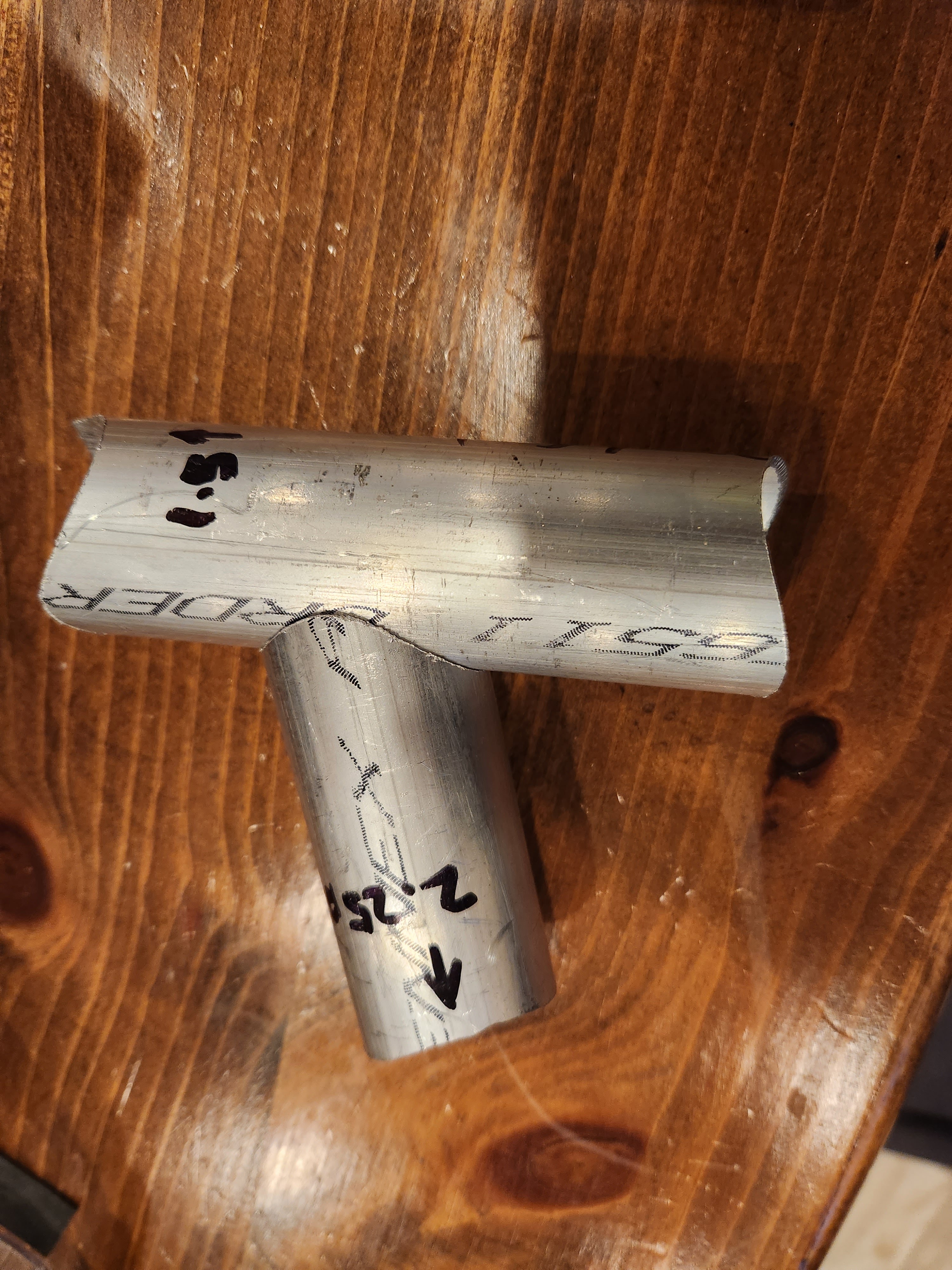
I've been wanting to do some structural analysis with the tubes that make up the front axle supports. I suspected that the wall thickness I chose for those tubes would be inadequate for the loads desired. I set up a separate file with just the pieces that make up the axle structure.

I set up pin constraints on the inner tube, associated the back plate with the front tube (blue dots) and added an upward force of 300lbs (1335N) where the wheel connects. The first study only had a safety factor of .7 LOL. My suspicions were confirmed. In the image below, blue and green are good. Yellow and red are bad. It looks like the max design load is putting too much stress on the tube intersections.


Thanks to the pipe tool in Fusion360, I was able to easily change wall thicknesses on the tubes. I ran  new analyses as I increased the wall thickness of the structural tubes.  I eventually got to a wall thickness that gives me a safety factor over 3. This structure will be heavier than originally designed, but will be stronger than a steel structure of equivalent weight (I also ran a study using steel tubes at the weight equivalent thickness).


The deflection shown is 2.6mm. I think this will work. 

Rudy March 21, 2023
Read more

 I'm exploring how the fat tires will actually mount to the CV axle. Turning down the splines on the axle seems like a waste to me. But to use them, I'd need some kind of spline hub that would attach to the fat tire hub. This could be the first part that I send to NanoAL. They are aluminum 3D printers!

3D printing in aluminum is just cool and I've been hoping something on this project would fit the bill. To make the model, I measured the width of the teeth and gaps of the splines and modeled the spline profile in Fusion360.


To make sure this profile fits IRL, I printed a test piece in PLA and fit it on the CV axle. 


It's almost perfect. There is a very slight wiggle, so I'm going to adjust a bit and print a few more until it's dialed in. Then, I'll add a flange, so it can attach to the fat tire hub. Once I have a working plastic prototype, I'll contact NanoAL to print it in aluminum.

Rudy March 20, 2023
Read more

 I've been updating many areas of the base as the planning of actual fabrication butts up against the virtual design. Our team machinist​ started milling the rear support plates. I also sent a CAM file to our machine shop captain for review. 


If everything is good (edit: it was not 😅), our machinist will run the part on the Tormach under our captain's supervision. Then I can set up other parts to be CAM'd based on this setup.

Rudy March 20, 2023
Read more

 I also tried out the tube notcher I bought.


It produces a nice, tight fit up without having to shape the profile with a grinder. This would've been so useful on Big Fish.

Rudy March 11, 2023
Read more

 I gave ​our team machinist some 1/4in flat bar yesterday! He's working on the clamp plates for the rear supports. 

I made one of the tubes for the supports in my basement as a proof-of-method.


Using the profile cutout worked well. But it will definitely be easier to make using the bandsaw at Lowell Makes.

Rudy March 11, 2023
Read more

 I completed the machine drawings for the 3 pieces that make up the rear support brackets!


I've seen a lot of videos where the welder draws a circumference profile on paper and then wraps the paper around a tube and traces the profile with a sharpie. Then just grinds down to the mark. 

I did the same thing virtually by converting my tube shape in Fusion360 into a sheet metal flange and unfolding it into a cut out then laying out the shape in the drawing at 1:1 scale. Now when the machine drawing is printed, we can: cut out the profile, wrap it around the tube to be cut and trace the desired profile onto the tube with a sharpie. Hopefully, it will make creating the bracket tubes a bit easier.

Rudy March 05, 2023
Read more

 It's still just a pile of material, but it's starting to feel real. I picked up the raw materials for the base. I bought extra, so I can practice and in case I mess something up.


Rudy March 04, 2023
Read more

 After almost 6 months of obsessing over this design, I think it's mostly ready for construction. There are a few phantom parts that had to be worked out. For example, I realized that I could extend plates from the differential supports to also support the steering plate and attach idler and tensioner sprockets for the front drive chain.


I also need a way to tension the  "road" belt. I came up with a tension block that would mount to existing points on the drive train frame. There is still some cleanup to be done before I can address those two requirements. And I still need to find a place to mount a tensioner for the rear drive chain.

But I've started creating to-do lists to capture all the tasks needed to build the base. This weekend, I want to begin making machine drawings for parts. Then, I will be reaching out to folks who expressed interest in fabrication and assembly. 

Rudy March 01, 2023
Read more