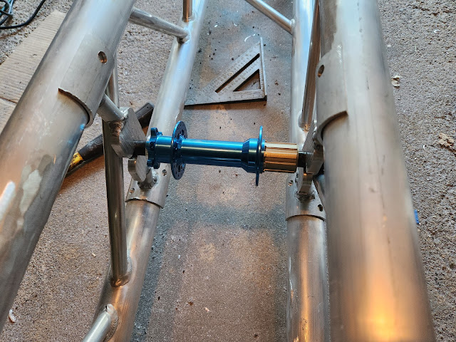
I dry fit everything we've made so far on the main truss. Everything mostly went together. The rear supports took a little convincing, but went in relatively easily. The front supports needed some light hammering to mount. Then. The issues. Since I assumed there were going to be issues, I wasn't surprised when I found some. 


On the front right side, I managed to install the gussets that we added to the front suspension upside down. smh. I now have to widen that hole in order to connect that CV axle to the differential axle. 

On the left side, the front suspension frame warped a little during welding. This pushed the top joint down a little over an 1/8" lower than designed. The knuckle binds when it rotates. This directly affects steering, so it cannot be ignored.

There are holes at the top of the knuckle brackets that the frame tubes fits into. I thought I would have to mill that down a little deeper, but after staring at it for a while, I realized there's an easier fix. 

The CV plate sits on ledges that are cut into the sides of the knuckle brackets. I think I can just remove another 1/16" from each ledge--a much easier operation. The knuckles should then fit in the space available and solve the binding issue. 🤞

For the rear supports, I used the new rear wheel hub to check the fit. At first, the hub was difficult to put in place. I realized that the welding beads on the back of the rear brackets were pushing against the truss' cross-members and moving the supports inward. Sliding the brackets down until the beads cleared, solved the problem.


Because each side of the truss' cross-members go in opposite directions, the axle bolt will need to be installed from the side after the wheel is dropped in place. At least we know the rear wheel won't fall off. 😅 

After all of that, I broke out my grinder to cut out the truss cross-members that are in the way of mounting the rear wheel.


The structure is now ready for the rear wheel. Of course, there is still one more step. There's always one more step. The new blue hub has to be mounted on the existing rear tire. This will require detaching all the spokes on the 26" tire, rebuilding the wheel with the new hub, and re-balancing the tire. 

That seems easy in comparison to other things we've accomplished, but I've never done it before and I have been stalling (i.e. doing other things first) 

I should be fine. I've watched this video, like, two times.


Rudy June 26, 2023
Read more

I spent most of last weekend in the machine shop. Progress has been slow but steady. Wheels have not been mounted yet, but hopefully they will be soon. We worked on preparing the rear wheel supports for welding. Our team welder, Jonathan, tacked those up and is working on them this week.


I tried to assemble the front suspension, but ran into a real world vs. virtual world discoveries. There was too much play where the tubes attach to the truss, making it very easy to pinch the thrust bearings at the knuckles. The knuckles (which support the front tires) need to spin freely or turning the sculpture will be impossible.

So we had to hold the attachment points at a specific distance and maintain the alignment between the top and bottom tubes.I was going to add tubular structure, but realized that the front axles run right through the area where the reinforcement would be located. We needed a brace that had a clearance hole in the middle of it. Jonathan suggested using plates instead of tubes. Great idea! Now, we just needed to make them. This sounded like a job for the Tormach!

I took some measurements, modeled the part in Fusion 360, and then created the CAM program to carve them out.


The fit up went well. Jonathan is also working to weld those pieces on this week. I also worked on the lawnmower differential.


This was the riskiest activity of the weekend. In order to get this to work with bike chain, I had to remove the large ring gear (the giant gear in the picture) and replace it with a sprocket. This would also remove some dead weight from the front. And I had to disassemble the differential in order to get measurements for mounting the sprocket. 

I thought the mounting hole locations on the sprocket might be a problem, but they mated up perfectly with the holes in the differential housing. Awesome! Problem one solved. The next problem was that the hole at the center of the sprocket was much bigger than the diameter of the axle rod. However, it had to be a loose fit hole in order to keep the miter gear properly located inside the differential housing. Another job for the Tormach! 

I measured up the dimensions on both the housing and the sprocket and modeled an adapter plate. I designed it with a hub to center the sprocket and a hole through it for the axle rod. I also added a matching bolt pattern so the adapter, sprocket, and housing could all be bolted together through the existing mounting holes.

Then I wrote the CAM and made the part on the Tormach.


Upon inspection of the housing, I noticed that the mounting flange had tabs sticking out on its edges. The original ring gear had a relief milled out to accept the housing flange with slots where the tabs stick out. When the differential spins, the ring gear turns the housing by pushing from the tabs transfer the turning forces instead of the pins/bolts that hold everything together. 

I decided I would also cut a relief out of the new sprocket to do the same. I measured and modeled again. Once I had the pocket I wanted, I wrote the CAM to make it. Since I only had one sprocket, I decided to do a test run on 1/4 inch aluminum plate.

Making a test piece was great. The housing didn't actually fit the first time.If I had run the job on the sprocket, I would've had issues. I adjusted all the dimensions to be slightly larger and tried again. This time it was a perfect fit!


Once I knew the relief would work, I then had to carve it into the aluminum sprocket. You might ask, "How did you hold the sprocket on the mill?" That was a question that perplexed me for a while. Then I realized I already had the solution.

The adapter I had just made had square sides and centered the sprocket. The only issue is that I couldn't use the existing bolt pattern to secure the sprocket because I was cutting through them to make the relief. So, I drilled and tapped a hole inside of that bolt pattern and used a shortened bolt (short enough to avoid the cutting head above it) to secure the sprocket to the adapter.

Milling out the relief was a lot harder than the test runs I did. The sprocket is black anodized, which gives it a tough surface finish that is apparently very, very hard. I had to slow down the feed to 2% (!) of the original, but I was able to cut the relief into the sprocket. The roughly 2 minute job on untreated aluminum plate took almost a half hour to complete on the sprocket.

I have to wait until at least Wednesday before I can work on the front/rear suspension. But in the meantime, I now have all the parts I need to mount the differential on the main truss! The parts all fit individually. Now we will see if it all goes together.


Rudy June 13, 2023
Read more

After some early success welding the inside joints, our team welder ran into trouble joining all the pieces of the front wheel supports together. Aluminum is very difficult to weld. 


The surface of aluminum is made up of aluminum oxide, a tough surface that protects the interior aluminum from corrosion. It melts at around 3700 degrees, hotter than the melting point of steel. The aluminum underneath melts at around 1200 degrees. So welding aluminum requires punching through the skin at high temperature and somehow not completely melting everything underneath. The analogy I was taught is that it's like welding a banana. 

At the same time, keeping extraneous gases out of molten metal is critical to the strength of the weld. Any contaminants that mix in while the aluminum is being welded will weaken the joint at best or make it impossible to weld at worst. He dealt with the latter for weeks. 

His experience welding steel helped a little, but it took him a lot of thought and experimentation to figure out his process. It basically boils down to obsessively cleaning all the surfaces with acetone between each prep step. 


After a lot of work, he completed the front wheel supports, but he might swear off working with aluminum forever.

We are almost ready to assemble the front suspension!


Rudy June 07, 2023
Read more