I completed a task for the front end of our racer! There's been a lot of movement on many of the almost two dozen tasks on that list, but none has been finished until now. I cleaned the grease from the lawnmower differential. I know, it doesn't sound like much. Until you see the difference.


I applied most of a can of Easy Off, attached a hose to the washing machine's hot water, and used a pressure washer attachment with the hose. I let it sit for 20 minutes then hosed it down with hot water. Then I did it again. It cleaned up rather nicely.

Generally speaking, a differential is what keeps driven wheels on the same axle from skidding sideways when a vehicle turns. The outside wheel has to travel farther than the inside wheel to keep the vehicle in the turn. If the drive wheels spun at the same rate, the vehicle would tend to twist and skid away from the turn and make vehicle handling problematic. To avoid that skidding, the wheel on the outside of the turn has to turn slightly faster than the wheel on the inside of the turn. 

The entire differential spins, but the shafts turn independently of the gear attached to the main housing (the ring gear). The shafts are also coupled to each other using bevel gears. So, if you hold the housing and spin one of the shafts, the other shaft spins in the opposite direction. 

In practice, if one shaft starts spinning faster than the differential (the outside tire during a turn) then the other wheel will automagically slow down the same amount to compensate and keep the vehicle from skidding. Now that I know all this, I look at my Subaru Impreza with new wonder.

Rudy April 18, 2023
Read more

Whenever someone points out something that I've thought of but dismissed (read, rationalized away), I take it as a warning that I should revisit it. This time, it's about how the wheel supports attach to the main truss. 

I had decided that using exhaust clamps to hold the support brackets in place would provide enough strength. The clamps "biting" into the truss tube would create creases that the clamps would sit in. He cautioned that vibrations could easily cause slippage under the right conditions and I should hedge my bets and bolt the supports directly to the truss.

These are exactly the thoughts I had when originally deciding to use clamps. But now someone else said it out loud, so it's not me overthinking it. 😅 I have extra 2-1/4" wide tubing that fits over the truss' tubes. Instead of plates bolted to the clamps, I redesigned it to use half round pipes that will be bolted in two directions.

Rear support with half-round tubing

Old design using clamps


I also made the same change to the front end.


I may run some stress analysis on the new rear brackets. But I think the front-end is set, since the simulations I ran on the front end previously show that the attachment point experiences the least stress.


Rudy April 17, 2023
Read more

I ran through the to-do list for the front end and published it to the team today. I updated the list to reflect the changes to the CV support bracket from last week (welding no longer needed to fabricate this part). 

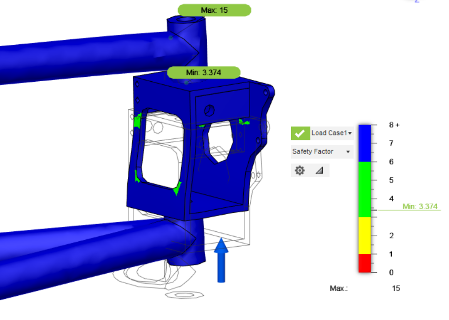
Before I can call the CV bracket redesign complete, I ran the same static stress analysis that I ran previously. The new design's safety factor dropped from mid-threes to 2.99. Officially out of the green zone, i.e. safety factor below 3.

Since the cutout only has to be wide enough to get the CV axle through it, I made the opening more square to increase the wall size at the top and bottom of the bracket. I also added another bolted-in cross-brace at the front of the bracket to increase lateral stiffness. The new safety factor came back 3.37. I think we can call the redesign done, now.

I also posted assembly and mechanical drawings for the front end to the to-do list. These should provide all the info to fabricate the front wheel suspension.


Rudy April 09, 2023
Read more

I bought more aluminum stock. I got heavier tubes for the front wheel support frames, with the thickness determined from the stress simulations I did previously. I also got some 3/4in flat bar for making CNC parts. 

I redesigned the bracket that holds the CV axle to use the 3in x 5in square tube stock that I have. In the previous design, I hoped to fit the CV joint through the space inside the square tube, but the inside width of the square tube isn't wide enough. 

Instead, I will cut a hole on the side wall that is big enough for the CV axle to fit through and mount the CV axle and brake calipers on the opposite wall. I think this design will simplify fabrication of the bracket. No welding is needed and there is less material compared to the last design. 

I'm going to run the same stress analysis that I did for the tubes with this new layout and confirm structural integrity. If the simulations work well, I think we'll be ready to make these. 


I want to make these brackets before welding up the support tubes, so we can use them as a jig during assembly and welding.

Rudy April 03, 2023
Read more

One of the reasons I like Fusion360 (besides that I've been using it for 8 years) is all the associated app features. Not only can I work out CAM operations to make stuff with CNC, but I can also do stress simulations on the geometry! Most of the simulation types are buried behind a $1400/year subscription (Yikes!) but the static stress simulation is still free. Works for me.

I've been wanting to do some structural analysis with the tubes that make up the front axle supports. I suspected that the wall thickness I chose for those tubes would be inadequate for the loads desired. I set up a separate file with just the pieces that make up the axle structure.

I set up pin constraints on the inner tube, associated the back plate with the front tube (blue dots) and added an upward force of 300lbs (1335N) where the wheel connects. The first study only had a safety factor of .7 LOL. My suspicions were confirmed. In the image below, blue and green are good. Yellow and red are bad. It looks like the max design load is putting too much stress on the tube intersections.


Thanks to the pipe tool in Fusion360, I was able to easily change wall thicknesses on the tubes. I ran  new analyses as I increased the wall thickness of the structural tubes.  I eventually got to a wall thickness that gives me a safety factor over 3. This structure will be heavier than originally designed, but will be stronger than a steel structure of equivalent weight (I also ran a study using steel tubes at the weight equivalent thickness).


The deflection shown is 2.6mm. I think this will work. 

Rudy March 21, 2023
Read more

 I'm exploring how the fat tires will actually mount to the CV axle. Turning down the splines on the axle seems like a waste to me. But to use them, I'd need some kind of spline hub that would attach to the fat tire hub. This could be the first part that I send to NanoAL. They are aluminum 3D printers!

3D printing in aluminum is just cool and I've been hoping something on this project would fit the bill. To make the model, I measured the width of the teeth and gaps of the splines and modeled the spline profile in Fusion360.


To make sure this profile fits IRL, I printed a test piece in PLA and fit it on the CV axle. 


It's almost perfect. There is a very slight wiggle, so I'm going to adjust a bit and print a few more until it's dialed in. Then, I'll add a flange, so it can attach to the fat tire hub. Once I have a working plastic prototype, I'll contact NanoAL to print it in aluminum.

Rudy March 20, 2023
Read more

 I've been updating many areas of the base as the planning of actual fabrication butts up against the virtual design. Our team machinist​ started milling the rear support plates. I also sent a CAM file to our machine shop captain for review. 


If everything is good (edit: it was not 😅), our machinist will run the part on the Tormach under our captain's supervision. Then I can set up other parts to be CAM'd based on this setup.

Rudy March 20, 2023
Read more