
While our welder has been working on joining all the front wheel support tubes, I turned my attention to the supports that will hold the front wheel differential in place. I last worked on these back in January. The original idea was to make a bunch of aluminum plates and weld them together. But then we started having some trouble welding the aluminum tubes. Since I had the time and I had started to think maybe we shouldn't try to weld everything, I decided to design a weldless version of the support. Yes. I altered the plan further.
.png) | ||
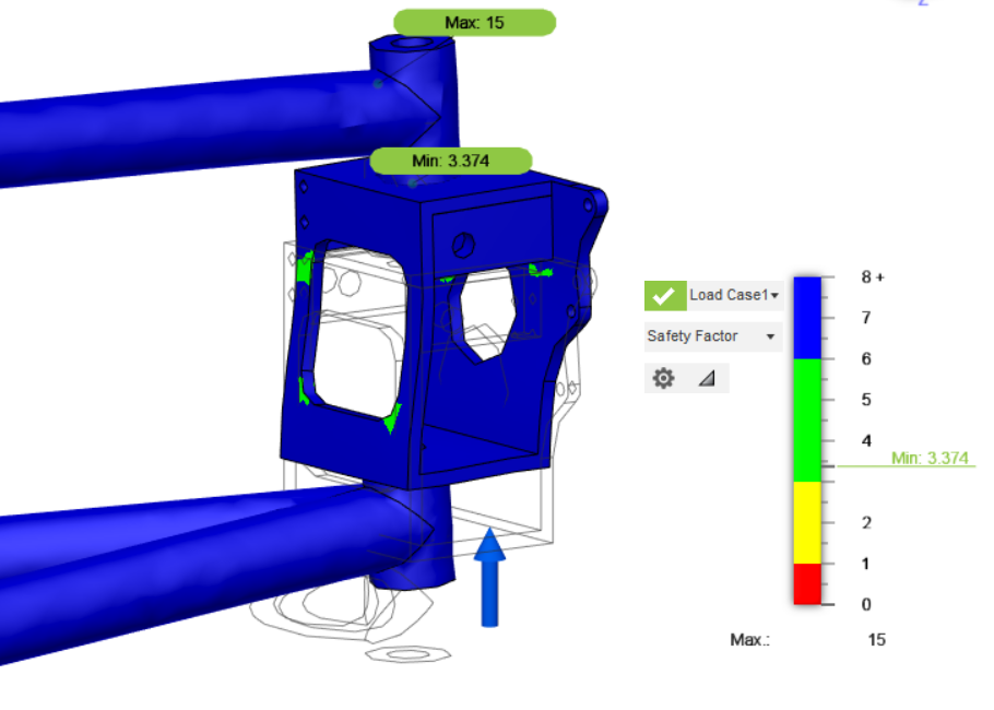
| The old, new design |

Instead of using ball bearings, I decided to reuse the original bronze bushings that came with the differential. They are much smaller so they don't need as much material to hold them. I first made a bed with caps to hold the bushings, but that turned out to be too hard to fabricate. The inside edges of the bushing pockets cannot be cut square, so I would never be able to finish making this part as designed.


Our machine shop captain suggested just making blocks and pressing the bushings into them. Then I could just bolt the blocks to a plate and bolt the plate to a support. That simplified things even more.


Now I "just" have to make the parts. I already finished one of the plates.

I tried to make the support brackets last weekend, but I had trouble with the CAM operations I programmed. The cutting operations IRL were a lot deeper than the virtual ones seemed and I ended up breaking my end mill bit. End mills are not cheap. The worst sound in the world is the cutting going from a high pitch hum of a good cut to the low frequency drone of a bad cut.
I will revisit that next weekend. In the meantime, I will make the bushing blocks on the CNC mill. These parts are simpler so the CNC operations are simpler.
We'll see what happens. 🤞


.png)
.png)
.png)

