During our successful road test, we not only pedaled up and down the street, but we also rode up the hill on the side of our house!


As exciting as that was, there's no time for laurel resting. We immediately turned our attention to the water.

99 problems and flotation IS one 

The race has a water obstacle. We have to roll into the water and climb a steep beach to get out. All of that and staying above the water require flotation. Last year, we used foam to float the Falcon (theoretically; we didn't actually make it to the water). I didn't like how much the foam obscured the guts of the sculpture. 


The mechanics are just as much art as the aesthetics. The veteran builders typically use inflatable pontoons; we decided to follow their lead. Andee sourced a very large inflatable raft with a 660lb weight capacity. It's longer than the truss and not too wide.  I thought it would work but to test it, we would have to ruin it as a raft. 

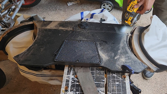
The idea was that the front of the raft would support the heaviest part of the Falcon while the side pontoons would support the pilots. To make it more stable, we would spread the back of the pontoons out to create a 'V' shape. To do that meant cutting out the back and most of the bottom of the raft. At least this would also remove some dead weight.


The test was straightforward. Inflate the raft with the Falcon on top, then climb on and see how far we sink. 


Everything went well. Because the raft was longer than the Falcon's frame, we were able to add supports at the middle and rear of the raft. This made it very stable, front to back. It easily handled the Falcon's weight, barely submerging into the water. 


We didn't spread out the pontoons for this test, so it was unstable laterally. We are confident that spreading out the back of the side pontoons will solve that issue. However, there was another issue that now needed addressing.

The raft sits under the main truss frame and is very tall. Because of the way the wheels are attached, they do not touch the ground when the raft is inflated. This is a problem because we have to roll into and pedal out of the water during the race. To solve it, we must lower the wheels 10-12 inches. And that requires upgrades (read redesign) to the front suspension. No pressure.
Rudy August 20, 2024
Read more
Steering has been a moving target (🥁). I had some early success with the control arms attached the the front wheel, but the human controls proved to be challenging. 


Handlebars had seemed to be the simplest solution for turning the Falcon. My knees would clear the handlebars while pedaling and the brake and shifters would have a natural mounting location. However, the range of motion of the steering arm, at greater than ±90°, was too large to use handlebars. They didn't run into my knees, but they did poke me in the ribs. This was not a workable solution.

Handlebars were actually my second idea. I went back to the original idea of using a steering wheel. I had previously bought a go-cart racing wheel last year that had a very flight-oriented look and also had a spot for mounting a handbrake. It would easily handle the range of motion, but this scheme needed a new place to mount the gear shifters. Since I already had to make an adapter to attach the steering wheel to the steering column, why not also use that to also mount shifters? 

I designed a simple adapter with a hole pattern for the steering wheel on one end and a square hole to lock onto the steering column at the other end. Most of the inside was removed to reduce weight. I carved a "saddle" into the neck of the adapter to match the profile of the original handlebar neck. 

I then mounted the handlebars on the adapter and the shifters onto the handlebars. This placed the shifters close to my fingers  (similar to car paddle shifters).

Using a steering wheel also required re-routing and re-supporting the steering column. Originally, it ran underneath the bike frame and connected directly to the steering arm. To get the steering wheel better aligned, I had to go up and over the bike frame. I secured the steering column using two haim joints. Haim joints are eye bolts with self-aligning eyes. They are mounted to the bike frame on threaded rods so the steering wheel location can be adjusted when needed.


The front wheels turn by tugging on a long arm attached to the left wheel, called a Pitman arm. It's attached to a steering arm that pushes or pulls on the Pitman arm when it turns.


Having the steering arm swing under the pedals was problematic. A mating bolt stuck out too much and intermittently impeded the pedals. This would definitely be a problem in the race, so I rotated the steering arm 180 degrees to avoid pedal interference altogether. But this created a different problem. 

Turning in the right direction

Rotating the steering arm 180 degrees caused the tires to be out of phase with the steering wheel. Steering left now turned the tires to the right! And steering right turned them left. 🤦🏽‍♂️ I tried for many days to find an in-phase spot for the steering arm, but the new location was the only way to get the full turning radius of the tires. I finally came around to it. I needed gears. 

Instead of attaching the steering column directly to the steering arm, I would connect them using gears. The steering column would turn a gear that drove the mating gear attached to the steering arm. It sounds complicated but a picture is easier to understand.

The gears needed to sit parallel to each other at a specific distance. This required yet another mounting plate and a new steering arm. I designed the mounting plate in Fusion 360, wrote the machining program to make it, and carved the part out on Lowell Makes' Tormach CNC mill.


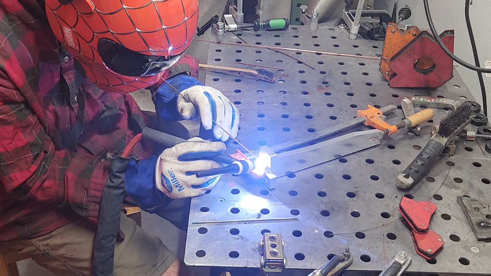
I made the three pieces that make up the new steering arm, mostly on the lathe and mill but also with a drill and hole saw. Then I welded those pieces together.

After installing the steering upgrades, I discovered another wobble that I did not anticipate. Instead of turning the tires, the steering column dances like a tree in strong wind. We need all the turning energy to get all the way to the tires.

I figured out that problem. There is a long shaft on either side of the universal joints. The top one is secured at two locations, but the bottom one is only secured at one. I needed to also hold the shaft higher up, but there was no easy place to mount this new support.

I decided to create a tall bracket to hold the shaft in place and secure it with the same bolts holding the gear platform in place. The bracket was made up of three pieces, welded together.

I used the existing plate and gears to align the support bracket, then finished welding it together.

Once I finished the tall bracket, I installed it on the Falcon. I think my designs are looking a lot more Star Wars!

Shifting into gear

The last thing we needed for the Falcon to move was to wire the derailleur shifter and attach the bike chain. I mounted the shifter and ran the cable to the derailleur under the seat.


The bike cassette is mounted slightly forward from the usual location. My first attempt at support brackets worked for a while, but aligning the brackets to each other was very difficult and eventually jammed up the axle. 

I realized I only needed to support one side of the cassette because the other side was already supported by the Hyperdrive frame. By using only one support, we avoided the alignment issues. I quickly designed a new plate that better clamped to the bike frame and produced it in record time.


Once the freewheel was re-secured, I wired up the front derailleur for a full transmission test.


I mounted the chain and checked the system.

The next road test

We were finally ready for the next road test. I checked the brakes one more time. I checked the transmission one more time. Finally, I checked the steering one more time. *#$^&*!$. The steering had failed again. What I thought was a loose set screw was actually a broken universal joint. The last universal joint in my possession. smh. The pins holding the joint together snapped off. There seems to be a lot of torque between the tires and the steering wheel.🤔


I really wanted to get to the next road test, already, so I fabricated a longer steering column to bypass the broken joint. It's not how I want it for race day, but it was good enough for a test.


Now. NOW, we were ready for the next road test.


All in all, it was a good test. The Hyperdrive upgrades are great! There was zero deflection of the drive axles. The chain between the freewheels and the Hyperdrive did skip a bit while coasting downhill. We'll need to take a look at that. 

The driver's side transmission works great! I was able to shift through the main range of speeds in both the front and rear derailleurs without the chain breaking or falling off. 

Steering...passed. I was able to turn the steering wheel, but it required A LOT of effort when the Falcon was standing still or moving slowly. We need to work out some kind of steering assist. I also think the breaking of the universal joint will not be a rare occurrence. We'll also need to beef up the steering in general.

All that being said, we cannot deny that the first transport is away!


Rudy July 30, 2024
Read more

When I work on the Falcon, I try to keep things as simple as possible. I really do. I mean, yes, I want all wheel drive and front wheel steering. But within that...simple. I'm learning and relearning that simple doesn't ever mean easy.

The Hyperdrive

The first test revealed that the drive sprockets were not correctly aligned with the wheel sprockets. Because of this twisted orientation, the beefy motorcycle chain would skip teeth and even fell off at one point. It didn't actually break, it just fell off.😅 It took some effort to fix this.

The "simplest" first step was to align the Hyperdrive frame with the wheel sprockets. I had to disassemble the entire drivetrain to do this. Every chain. Every sprocket. 

First, I centered the frame over its supports. This works to shorten the unintentional lever arms. Shorter lever arms equals less bending force. Then I repositioned all the frame support clamps to align the orientation of the sprockets on the Hyperdrive with the wheel sprockets. I also flipped the sprockets when I remounted them, so the teeth were as close to the frame as possible. 

During the next test, I was able to get further with these upgrades, but only just. See if you can hear where things started going wrong.

The main transmission axle was secured only in one place. Under pedaling force, the free end flexed like a dog's tail during pedaling. I had reduced the bending forces, but they were still large and unrestrained.

The bright side was there was enough force to bend, but not permanently deform, a half-inch thick aluminum plate. That's a lot of power. But I needed that power to go into turning wheels, not bending frames. In order to prevent tail wagging, I designed a simple (there's that word again) gusset to add to the Hyperdrive frame.

This "simple" gusset took an entire weekend to fabricate. I used the force-multiplying Tormach CNC to make the fins while I made the tube piece on a lathe and the cross plate on the knee mill. I would've carved it out of a single block of aluminum, but I didn't have the extra material.

I welded all the pieces together...badly. I really wish I had had that block of aluminum to carve. It would have been so much prettier. 

I then welded the new gusset onto the back of the Hyperdrive frame.


The plan was to secure the new gusset with the "lollipop" truss clamps already being used elsewhere on the Hyperdrive frame. However, I biffed the length of the gusset, and made it too short to use the lollipops. I ended up using the base of one of the lollipop clamps and fabricated another zero-clearance clamp that I had designed last year.


The Hyperdrive is ready for another test, but the Falcon is not quite ready. We've also been trying to finalize steering. The original handlebars idea will not work, so we are working on adding a steering wheel. Yet another example of simple not being easy, but we'll get into that in the next post.

Rudy June 28, 2024
Read more

I took the Falcon outside for a road test today!

I spent all winter giving the Hyperdrive a steel heart and this was the first test of the new design.

The Hyperdrive's Steel Heart 

The original Hyperdrive design had lots of twists and turns, so the frame has many mounting points, some of them adjustable for tensioning.


Because of this, I was able to try out many combinations of sprockets and chains and tensioners, until I found a combination that worked.


The final configuration coupled the front and rear wheels together in a simple way.


The road test revealed that the rear sprocket deflects under high torque enough for the rear wheel chain to fall off. We'll need to shift the frame's location to the right to fix the problem.

Steering

We're using handlebars to turn the wheels. They mount to the seat tube of the driver's side bike frame. A steering rod connects the handlebars to a linkage down near the front, left tire.


I made the steering stem adjustable, so people of different sizes can pilot the Falcon. But there's slop in each of the two universal joints and the sliding joint. Because of that, the handlebars have a lot of play. I can move it 5-10 degrees  without affecting the tires. I think l'm going to put in a fixed length steering rod, but I also need to source stiffer universal joints.

Pedal Rear Derailleurs

The pedal's rear derailleur also needs some work. Its attachment point isn't stiff enough, so the chain falls off intermittently when in the lowest gear. I also think the width of the bike chain I got is too thin, causing it to stick on the derailleur. I'm going to try a slightly wider chain to see if there's a difference.

One Good Test

The one highlight was testing the low gear by climbing a 4 inch curb!


The Falcon was also going uphill (and that rear tire looks a little low). Once I resolve the remaining issues, it'll work even better.

May the 4th be with us!


Rudy May 04, 2024
Read more