I often show the Tormach making the parts, but there's more to the process. I design the part in 3D, then I write a program to carve the part out of stock material. I then have to mill stock material down so that it's the same dimensions or slightly smaller then the carving program expects. I have to precisely set the X, Y and Z axes and measure the heights on all the cutting tools used. After all that, I can finally run the program that makes the part. These are all the steps I take when I say the part was "straightforward" to make.

The two lever-assist arms were straightforward to make. After setup, I was able to make both of them in one afternoon. That's the best feature of the CNC mill. I can make the same part over and over, but I usually only have to do the setup once.


The Final Four

Previously, I described the suspension as a seesaw. The wheel is attached to one end of the seesaw and the other end is pinned to the central frame. A lever arm rotating around a fulcrum moves the seesaw, pushing the wheels into the ground and lifting the front end. The last four parts to be made were the two lever arms and the two fulcrum brackets. 

The original design of the lever arm was pretty basic (shown above). Before I actually made these parts, I redesigned the interior of the arms to look a little more Star Warsy. I always say that, to me, the engineering is the art and this was a great example. Each arm took most of a day to run, and they came out really cool!


The fulcrum bracket is the physical connection between the chassis and the point in space where the fulcrum is located. The lever arms attach to and rotate around the fulcrum bracket. I designed a simple bracket oriented at an exotic angle. Two long tubes connected to the chassis and also to each other. Because the tube intersections created complex profiles and because the placement and shape of those profiles had to be fairly precise, I used the Tormach to make them before I began carving out the lever arms .


I also made the cross-pieces for the fulcrum brackets–the attachment plates and pivot tubes–on the lathe at the same time. Once the pieces were made, I set about welding them into brackets while the Tormach worked on the lever arms. 

First, I clamped up and welded the attachment plates and pivot tubes onto the ends of the long tubes. Those connections were perpendicular, so I only needed one clamp to hold them together.


Once the pieces were welded onto the long tubes, I then had to arrange and hold the long tubes at the correct angle. Getting them positioned correctly took some effort.  I did have a short truss that was the same shape as the Falcon's truss. I was able to use that as a jig to prepare the final joints.


After clamping the long tubes to the truss using hose clamps, I used angle gauges to set the 34 degree angle between them. I moved the two legs around until they were snug up against the gauges.

I spent a lot of time getting this angle right. If the fulcrum ended up in the wrong spot, it would make assembling everything much more difficult. I checked the position of the brackets relative to the chassis by putting a level on the chassis, then putting the level across the fulcrum tubes, and comparing the reading. Everything lined up.

I tack welded the last joint on each bracket to make sure they did not shift while I worked on them. Then, I began to weld. The TIG torch had sprung a leak and could not be used, so I had to use the MIG welder instead. MIG is an ax to the TIG's scalpel. TIG melts and you add metal in small drops. MIG adds metal as it melts. I had to be extra careful. I could easily add too much metal or worse, burn holes into the tubes.

The perfect TIG technique refers to "stacking dimes," or laying out the beads so they overlap each other. If you do it right, your welds look like a necklace. I have flashes of competency, but my TIG welds are usually very ugly. Since I had to use MIG, I decided to try to fake the dimes. As the machine fed out wire, I made small, circular, overlapping motions.

I slowly made my way around all the joints, taking breaks to let the metal cool down, until the brackets were completed.

With that, ALL 36 parts for the new suspension were fabricated.


Next up, put all the pieces together to see where reality differed from virtual. For the Glory! 


Rudy July 17, 2025
Read more


After fabricating most of the interior parts of the new suspension, I tackled the parts that make up the knuckles. 

What's a knuckle? The knuckle mainly holds the wheel in place but also allows the tire to rotate on three axes. Not only can the tire spin and turn, but the knuckle also allows the entire assembly to rotate when lifting the front end. Our knuckle is made up of a bearing plate, two knuckle brackets, and two pivot brackets.

We've had a version of a knuckle on the previous two designs. The new design has an extra degree of freedom. I also added a lip to the bearing plate to prevent the bearings from squeezing out--the issue that ended our last race. I rounded the back of the knuckle brackets so we could get ±45° of turn. I also thickened the bottom of the bracket to better accommodate a bearing.

The new bearing plates were done previously, so I began this push with the upgraded knuckle brackets. I manually machined aluminum stock to the dimensions I needed to carve the parts out on the Tormach.

Because these brackets are one of the smallest of the CNC'd parts, I was able to make four of them on the same day. Until now, most parts have taken a day each. After the main parts were done, I used the manual mill to add mounting holes needed to connect the knuckle brackets to the steering components.

The pivot bracket was another story. This bracket has to attach to and rotate around the suspension legs while also attaching to the other pivot bracket above it, and also support the knuckle brackets. In order to accomplish all this, I had to run setups on four sides of each aluminum block. Usually, only two sides are machined to make a part. The top side "Han in carbonite" setup carved out most of the parts' features. I had to use extra long end mills to reach all the surfaces.

I then moved on to the features on the sides: a through-hole larger than the 3/4-inch threaded rod going through it, and a "cup" for a bearing. The two sides, though, had to be aligned with each other. I used the newly machined top and back faces to set my origin for both sides. Because both surfaces were machined, I was fairly confident that the starting point for each side was the same. 

Both setups ran the same operations. First, the bearing cup was carved out. Then, the clearance hole was bored. I didn't have an end mill long enough to get all the way through the part, so I only went down halfway on the clearance hole. 

There were slight variations between the two sides, but it was small enough that a 3/4 inch threaded rod still fit all the way through the part. And that's all that we need. 😎

The last setup was for the bottom side of the part. Weight is always a concern, so I removed most of the extra material and left a cross pattern centered around the knuckle bracket mounting hole. The "T" cross-section will help minimize flexing of the bracket's "floor".

With the four knuckle brackets and the four pivot brackets completed, we are now 83% done with the build! Not far now.

The last six parts are on deck. These parts include the arms that actuate the scissor lift function and the brackets that the arms rotate around. There are aluminum and steel parts, and I'll need the Tormach for all of it. 

For the Glory! 


Rudy July 08, 2025
Read more

Work on the Falcon's suspension system continues. I usually try to maximize my time when I'm in the shop. While the Tormach mass produces the more complex parts, I work on the parts that can't be made that way. This time I tackled the custom hangers.

The suspension system is basically a seesaw. The hangers hold one end of the seesaw at the correct position and provide the tension needed to hold everything together. They are made up of two bearing tubes and two spacer bars. 

I first tackled the eight bearing tubes. I cut steel tubing roughly to length on the bandsaw and turned the ends down to size–pretty easy to do on the lathe. I also widened the inside of the tubes slightly so the bearings would fit.


The spacer bars were harder. The distance between the bearing tubes had to be the same for all the hangers. I needed to make these on the Tormach, but there was one problem with that. The finished part was shorter than the vice holding it, so I couldn't mill both sides in a single setup without cutting into the vice. I'd have to do it in two setups.

In the first setup, I milled the desired profile into the free end of the bar and then milled a small hole on the other side. Why a small hole? Since I had to take the part out of the vice and turn it around to finish it, I needed a way to reorient the bar and set an origin for the second setup. The hole provided this function.

To set up the other side, I mounted a gauge pin on the Tormach like a drill bit. Then I slid the bar over the pin, auto-aligning it with the machine. I locked the bar into the vice and set the machine's X and Y axes to zero. Then the Tormach cut the second profile while also removing the registration hole and finishing the part. I repeated those steps seven more times.


Once I had all the pieces, I was ready to weld them into the final parts. I machined a gauge block to ensure the correct spacing between the bars, then clamped up each assembly and tack-welded all the hangers together.

I'm getting a little better at welding with all the practice. The thing I'm learning most is patience. Instead of trying to weld everything everywhere all at once, I welded a quarter of the way around on each bar. Then I let each hanger cool off before welding it again.

I still seemed to overheat the metal periodically, causing porosity when the molten metal hit dirty air. I had thought it was because of the air inside the tube, but I later discovered that the torch had sprung a leak. Not enough gas was flowing out of the torch to create the curtain of inert gas necessary to form strong welds, causing all the pock marks (porosity).

I eventually switched to the MIG welder to finish welding the parts, but that added the extra step of cleaning up the welds with a grinder.

The last step was to clean up the inside profiles of the bearing tubes. I had smoothed them out on the lathe when I made the bearing tubes, but welding always deforms the metal a little bit. I used the ever-versatile Tormach to re-contour the tubes.

With these four parts, the suspension system build is 61% complete!


Rudy June 30, 2025
Read more


Fabrication of the new suspension continues. I made the last of the hanger brackets, so we can now officially attach the new suspension to the Falcon!


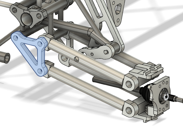
I also made the next four parts in the build: the alignment bracket that keep the hangers and the suspension arms in the same position, relative to each other.

These were deceptively difficult to make. First, because of their size, I had to hold them in the machine differently than usual. That wasn't too bad. I just moved the jaw bolted to the front of the movable block on the vice, onto the rear position.


Carving out the first side of the part went well. I like to call this the "Han in carbonite" phase.   

I was able to remove all of the interior material without cutting through the bottom of the stock plate. The stock I used is 3/4 inches thick and the bracket is .7 inches thick. That 0.050 difference made sure I didn't accidentally cut into the vice. Because the vice jaws were in the way, I couldn't cut along the outside of the part. That left the bottom .25 inch thickness of material to avoid that.

I usually just flip the part over and remove the "carbonite" layer to finish the part, but since I need to maintain bracket thickness I also had to precisely trace the outline of the part from the other side. That's why there was one hole cut all the way through the first side. That hole became the origin for all the flip side operations.  

I began finishing the second side by manually cutting away most of the extra material using a bandsaw. It didn't take very long and helped reduce CNC machining time.

Because the part is triangular, I had originally planned to hold it along the hypotenuse but that wasn't possible. In that orientation, the part is not wide enough for the vice to hold it. And, yes, it was also too wide to move the vice jaws back. smh

I was stuck. To finish the part, I needed to make a custom jig–a part to finish the parts. If I could clamp the jig in the vice I could then secure the triangular brackets to the jig. I began with a 6 inch by 6 inch stock plate and designed the jig to use the central trapezoidal shape of the part to keep each bracket from shifting or rotating. I added 1/2" threads so I could lock each part down onto the jig with bolts.


Using bolts on the inside of the part meant that I couldn't use the Tormach to finish the back face of the bracket, so I did it manually. I had to keep the face mill moving to avoid tool marks. It reminded me a bit of playing the drums.


Once the jig was complete, I slipped each faced bracket on, bolted it down, and cleaned up the outlines.


The jig made easy work of finishing the alignment brackets.

With these parts, we are 50% through the build!

Next up, the parts that attach the wheel to the suspension and all the remaining steel structural pieces. For the glory! 


Rudy June 03, 2025
Read more