I worked on the brackets that will secure the front differential to the main truss. They would be made out of flat plate (probably fabricated on the Tormach CNC Mill at Lowell Makes) and welded together. They would be bolted to the frame in 3 places.


The space between the brackets where the sprocket is located is the width of the differential that I measured from the housing, minus the difference in the thickness between the original ring gear and the sprocket that will replace it.

Cleaning the differential is going to be a messy job that will require a pressure washer using hot water. I'm going to wait until it gets warmer to do that job in our driveway. After it's clean, the pins that hold the ring gear to the differential will be drilled or pressed out. 

Hopefully, the holes can be reused to attach the front drive sprocket to the differential. The differential axle will be attached to the CV axle with universal joints. Universal joints should work, since the angle between the two axles will always be small.

In the meantime, I am working on the last front-end issue: where the CV joint meets the wheel. 

This first idea would cost way too much to fabricate and would probably be too heavy, even in aluminum. 

I'm thinking about using some kind of C channel or bracket. The CV joint would sit on a bearing mounted to the back of the bracket. The legs of the 'C' would be bolted to the frame with thrust bearings (or maybe headset assemblies from mountain bikes) supporting the hub.

This is the area with only the required pieces showing:


The eye bolt attaches to the tie rods used for steering and has to be at a specific angle to the CV axle. The CV axle is supported by the bearing. To use headsets from bikes, the frame ends would have to be tubes. But if we use thrust bearings, it could be a plate (probably gusseted).


Rudy January 28, 2023
Read more

 I opened up the transaxle! The layout of the parts inside is a little different than I imagined.

The ring gear is a largest spur gear and it's riveted to the differential housing, acting as an endcap.

It will be difficult to remove that gear to replace it with the 36 tooth sprocket. But if I can drill out the rivets, I think I can use those holes to bolt the sprocket to the differential housing.

The shifter plate has square slots, so I'll have to make my own shifter plate to interface with the pins I want to press into the drive pulleys. At least I will be able to use the arm that slides the shifter plate along the shaft.

There are also bevel gears in there that I need for the water jet project. All in all, a pretty good haul.

I also measured everything inside the casing, so I can now work on finalizing the front end.

Rudy January 22, 2023
Read more

 I removed the rear axle from the lawnmower! 

Two bolts were the only thing holding it on. Once I took those off, I was able to get the belt off without too much trouble. 

The tires still have to come off. The bolts holding them on did not loosen on the first try. I'll take another shot tomorrow from the comfort of the sealed garage. Then, it's time to crack open the case to retrieve the differential, the shifting mechanism, and the bevel gears inside. The front end can be finalized once we have these pieces.

I also fit the 28 tooth sprocket onto the hub-conversion brackets. 4 of 6 fit easily. But 2 of the holes were not on the same bolt circle. I enlarged those 2 holes enough that I can now secure all 6 bolts.

I've been finalizing the rear mounts. I think we're close to making the parts that will secure the rear wheel to the main truss.

Rudy January 21, 2023
Read more

 I got the new rear hub yesterday! It's pretty.


I also received today a single speed conversion kit and a 28 tooth wide sprocket.


I need to confirm if the sprocket actually fits. Otherwise, I'll have to find a sprocket that I can modify.

Rudy January 18, 2023
Read more

 I spent 2 hours on saturday studying the lawnmower frame and how to detach the rear transaxle. I found and removed 4 bolts that attach the transaxle to the frame. 2 came off easily. I had to cut the other 2 off. There's a belt that goes from the engine to a pulley clutch and another belt that goes from the clutch to the transaxle.


I can loosen the big belt with the clutch, but I haven't figure out how the belt comes off in one piece. There are tabs acting as guardrails that keep the long belt in place. I can't seem to remove the belt without bending the tabs out. Seems like there is another way. I'm going to do some youtube research before I do anything with that. I might not have to touch that anyway. Other than detaching some springs, I think the transaxle is now only attached by 2 more bolts.


I think if I undo these bolts, I won't have to mess with the belts at all.

I spent the rest of Saturday fixing my virtual model of the center truss. The IRL frame has 9 cross-members. My model had 10. I spent most of Saturday taking measurements and trying to make my model match. It's tricky, because I can't measure to the center of anything. I have to estimate based on the distances at the intersections. 

I'm glad I did, though. I already have to shift some things around in front because of the slightly different geometry.


Rudy January 16, 2023
Read more

 I spent the free time I had last week working on the shifter box design. "Easy" removal of the belts in the box is my main design requirement. Everything I've come up with before now would have required removing the housing to install or replace belts. It seemed like the only way to maintain the rigidity of the housing. 

But then I tried designing the housing using sheet metal and bending everything into place. This also gave me another chance to play around with F360s sheet metal tools. This is what I have so far:


The long tab would be welded to the transmission frame. This would also be how the transmission frame attaches to the vehicle frame. The right side of the box would also be welded to the frame for stiffness. The tabs in the front and top of the box should keep the two pulleys from sliding when the shifter plate moves between them.


In this setup, the two gears are mounted on the main freewheel axle. There is no direct contact between these two pulleys and the shifter box (except for the anti-slide tabs). Here is the sheet metal flat pattern


I had to break out some graph paper and scissors to work some of this out. 😅 The slanted part of the box will eventually have a slot for the shifter pole. That is still dependent on what's inside the lawnmower's rear axle.

Rudy January 16, 2023
Read more

 I noticed (and just confirmed) that the two fat tires I possess both have front wheel hubs. But I need a rear wheel hub for the racer. I went looking online yesterday and they are surprisingly hard to find. I eventually searched for "rear hub 197mm 32H" to find what I was looking for. Most of them are pricey, but I found a closeout sale for this hub for $21! (regular price $180).


https://www.the-house.com/qfrthaxr197bkzz-framed-bike-hubs

In case anyone is looking. 

Also, the stage truss that is integral to the design has arrived! Comparing the actual truss to the virtual one. It mostly matches up. The only difference is it has 9 cross-members (my model has 10). The virtual has ten. Now I must update the truss model to see if I need to adjust anything. Mostly I have to make sure that the cross-members aren't in the way of anything that needs to run through the truss, like drive axles.


Rudy January 12, 2023
Read more

 I looked at the lawnmower again today. It looks like the shifter and differential are both part of the same assembly. And that seems like it's held in place by 4 bolts.

Let's see if I can take the rear axle off during the week so I can dive in next weekend.


I also ordered the stage truss that will be the base of the whole vehicle. It probably won't ship until tomorrow. So exciting!

Rudy January 08, 2023
Read more

 Someone asked me why I was using belts for the racer's main drive. Kinetic sculptures apparently don't really use belts and pulleys. My main motivation for using belts is gearing down significantly while minimizing weight.  Doing that with chains and sprockets would be so much heavier. I also want to reduce the lengths of the tire chains where possible.

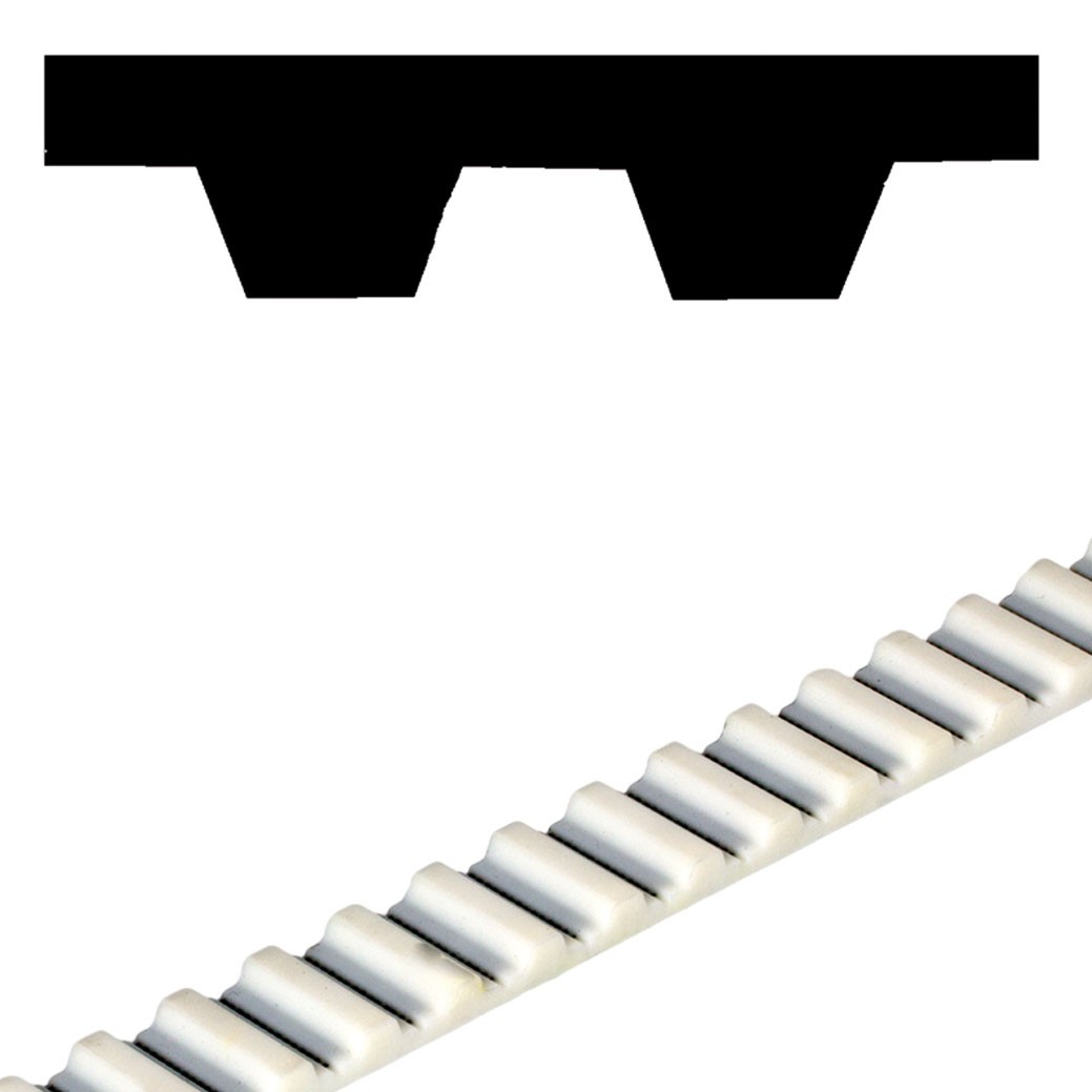
The pulleys I sourced from Maedler North America are made from aluminum. The belts are steel-reinforced urethane belts and have trapezoidal teeth. The specs I've read just require that the belt engage 6 teeth on a pulley to get the rated capacity.


There would still be chains from the pedals to the drive shaft and from the drive output to the tires.

We had to do a lot of repairs during the race last year, so in-race maintenance is a top consideration, trumped only by weight. Though it's not bicycle tech, this technology is used in cars and other transmissions. As long as we get properly rated belts, I think it'll work.

No special chain tools would be needed to change belts. Just a wrench (maybe a ratcheting one to maximize efficiency). 

All the mud gear belts are the same size and can be changed by loosening 2 nuts. The long belt can also be changed by loosening just 2 nuts. It's about the same price as the 4 mud gear belts. Switching the 2 drive belts would be a little more work, since it would involve opening the shifter box. Tightening the belts would be done by adjusting 4 nuts.

However, putting new drive belts on would require opening the shifter "gearbox". I'm working on the shifter design currently, so that process is still a little vague in my mind.

Lastly, I want to use beefier chains (40b) than standard bicycles to connect the drive to the tires, in order to handle the torque being generated in mud mode.
Rudy January 06, 2023
Read more

I spent the rest of my down time thinking about the drive mechanism. The belts and pulleys I want to use are from Maedler North America. I've kept the front half of the pulley layout the same, but I've decided to couple the front and rear sprockets to each other using the longest belt I could find (1440mm!). This will lower the amount of hardware needed to complete the drive. But it will also give me the points from where I can drive the wheels at the two different rates (road and mud).

Here's the design so far:


Here's what the long belt loop, the road gear currently looks like:
The orange dashed lines are idler pulleys that I sourced, but don't have a model for. They would be mounted on jack shafts and would spin freely. The position of the idler all the way on the left would be adjustable along the axis marked by the black line, so the belt can be tightened. This is the "mud" gear:
The two pulley sets floating in space will be connected to the frame with long bolts to make them adjustable, so those belts can be tightened. The belts are all the same length. The long belt and the mud gear belts are both attached to the front wheel sprocket. 

The shaft that is driven by the pilots runs through the "Y" frame in the middle and has two pulleys that are engaged independently from each other. Here is the "road mode" drive belt:
And here is the "mud mode" drive belt:
I've been wracking my brain over how to switch between modes. The gears have to spin independently of the shaft they are sitting on, and somehow still engage the shaft on command. Everything I've seen about transmissions uses elaborate bushing and expensive gears. Then I went back to the lawnmower I acquired. It has a shifter with forward, neutral, and reverse. 

A quick youtube search on lawnmower transmission brought me to this:

This guy cut open the housing, cleaned all the parts, and then explained how the whole thing is put together. The relevant part is around the 3min mark. The shifter plate spins with the shaft and couples to the output gear using two metal pins that lock into holes drilled into the side of the shifter plate. 

I think I can use this same idea to shift between mud and road. I would drill two holes into the side of each drive pulleys and press pins into them that align with the holes in the shifter plate. Then, moving the plate left or right would engage one mode or the other. Here's the gearbox, so far:


I think the shaft probably needs to be a d-shaft and the shifter plate would need a slip-fit d-shaped hole. The plate can't be secured by set screw, since it has to slide back and forth freely. I could probably use a round shaft and grind flats into it in the right places, but the shifter plate would need a set screw low enough to engage the flats.

Rudy January 05, 2023
Read more

I worked most of the holidays but the time off I did take, I spent thinking about the new racer! 😜 I'm almost done cleaning last year's projects out of my garage, including Big Fish. 

It's turned into a full blown reorganization (or just organization) of the whole space. I built a pegboard wall out of extra deck materials, trimmed a window with a ledge, and added a 10-outlet power strip for charging batteries, etc.

Half the wall is for all of my landscaping tools that have been mostly languishing on the garage floor until now. The other half now holds all the parts unpacked from the boxes and bags of deconstructed Fish. I now have a mini bike shop in my garage. 

I need one more weekend to remove what remains into a dumpster, but then. THEN, I'll be ready to get to work pulling parts from the lawnmower (from the comfort of my garage).


Rudy January 05, 2023
Read more