We're firing on all cylinders now. I mean, I'm desperately trying to keep all the spinning plates in the air. Race day is one month away and there's still a lot to do. We've made more progress on the front wheels, seating, pedals, and we've started the "canopy."
Front Wheels
I finally finished the last two pieces that secure the front fat tires to the CV axles: the outside bolts that screw directly into the CV axle. It was my reacquaintance with the lathe. It was not rudimentary.
The first one took a while and had a lot of chatter. It's not supposed to chatter. After our machine shop captain pointed out all the dumb things I was doing (my words, not his), the second one took half the time and hardly made any noise. The highlight of the job was drilling and tapping an M16 hole in the stainless steel bar. I had to walk through 6 different progressively wider bits to get up to the 14.5mm diameter pilot hole. I also used the lathe to tap the hole.
The CV axle threads onto the bolt nice and easy, like I planned it. 😎
I then had to mill flats into the hub bolts so a wrench could be used to tighten them down. It took a couple of tries. During my first attempt, I did not set up the part very well and burned out my end mill before I realized. That's when the tool gets so hot that it melts the material instead of cutting it.
Turns out I was spinning the end mill too slowly, milling in the X direction instead of Y, and taking too shallow a cut per pass. Our machine shop captain informed me that a shallow depth-of-cut concentrates too much heat on the corner of the tool, quickly destroying its sharp edges. So that's how it happened. It makes sense when someone with a ton of experience says it. 😅
SO, spin twice as fast, use more of the side and less of the bottom of the tool, and work in the Y direction. I also centered the part in the vice and used the mister to spray coolant on the end mill while it cut. The new parameters did the trick!
The inside surface of the hubs I purchased had a small lip on the outside edge of the tubes. They need to be smooth all the way through so the hubs stay in full contact with the axle spacers and bolts. Otherwise, the wheels would probably wobble. I used a Dremel tool to grind the lips down flush. All the parts now slide snugly into the hubs.
The last manufacturing step is to assemble the hubs and axles then drill holes for clevis pins it's just the "simple" task of rebuilding the front wheels. I did this for the first time ever with the back wheel. Hopefully, that experience will make these next two wheels a little easier.
Seating
I worked on the structure that supports the seats. Two thick aluminum tubes are attached across the main truss. They are notched and bolted in place. Steel angles are bolted to these tubes to support the seats.
We are using the seats from last year's sculpture, Big Fish. Other than some bicycle hardware and loose PVC, these were the only things to survive deconstruction..
However, to use the seats they have to be modified. They need to be freestanding and slide on the steel angles so pilots can adjust their position relative to the pedals. The seats need to be on rails
I cut and shaped rails from the same electrical conduit that we originally used to make the seats (more deconstructed material from Big Fish) and notched them so they fit snugly up against the existing seat frame.
I was having trouble lining the tubes up to drill the notches until I made a jig using the steel angles. I just screwed the angles down to a couple of scrap pieces of plywood. Keeping all the pieces aligned was much easier with a jig.
Once everything was notched and dry-fit, I then carefully welded the new tubes to the existing seat frames (without melting any of the seat material!).
Now the seats are freestanding and they're adjustable.
Pedals
The sculpture still needs pedals to make it kinetic. We were originally going to make custom frames, but time marches on. After a couple of visits to The Bike Connector's junk pile, we were able to find two aluminum bike frames that were destined for the scrap heap.
I did some work figuring out how the frames should be oriented and how they will attach to the Falcon.
The bike frames will tilt back like they are "popping wheelies." The pedals are placed so the pilots can use them recumbently. The freewheels will end up under the seats and roughly line up with the input shaft of the Hyperdrive. The seat post is a great spot to mount the steering wheel!
Canopy
We've been talking about the kinetic part for so long, you might think that we forgot about the sculpture part. The canopy will give the Falcon its look.
We started with the giant loop that makes up the Falcon's saucer. I turned to Jen, one of the members at Lowell Makes, who makes lyras out of steel tubing. She graciously spent the better part of a day teaching me how to bend tubes. I learned a lot from her, enough that I think maybe I could do it alone. Haha.
We used a tube bender with a motorized attachment to shape the large outer circle of the canopy from super-thin aluminum tubing.
It took three 8-foot tubes to make the 80" ring. 😎
I made custom collars to join all the seams. This should make it a little easier to weld.
Next, we will attach all the straight pieces: the mandible tubes and the support structure for when it's attached to the base.
To get the canopy to look like the Falcon, we plan to build a thin cage on the canopy frame and lay out "cosplay" foam sheets over it. We'll layer the foam to build out the surface features. The more accurate we are to the scaled up features, the better the canopy will look. But we don't have time for too much experimentation.
I came up with an idea to hopefully lay everything out to scale without too much work. I purchased a model for 3D printing the Falcon. It's actually a bunch of models that you can print out and assemble a 16-inch scale model in plastic. I imported all the pieces into Fusion360 and scaled everything up to the size that we will need for our sculpture.
Then I created full-scale drawings of each section and its features. Here's one for the half of the drive section in the rear (in purple)
We'll print them out on large sheets of paper and use them as patterns to trace onto the foam sheets. It's going to loook awesome!🤞
Truing a wheel refers to aligning the rim in relation to the hub by tightening the wheel's spokes. My first attempt was trash. There was a pronounced egg shape radially and the sides of the rim wobbled back and forth. I didn't have a truing stand and Lowell Makes' stand wasn't wide enough, so I tried to true it by eye. Like I said, trash. I started over.
I loosened and/or replaced all the spoke nuts and watched more videos on lateral and radial alignment. John at The Bike Connector suggested that I mount the wheel on it's frame and use that as a truing stand. Brilliant! And something I should have realized myself. SMH
The videos were very informative. They used the adjustable indicator on the truing stand to find the high spots on the rim while it spun, mostly by ear. The rim made a slight scraping sound whenever it touched their indicator.
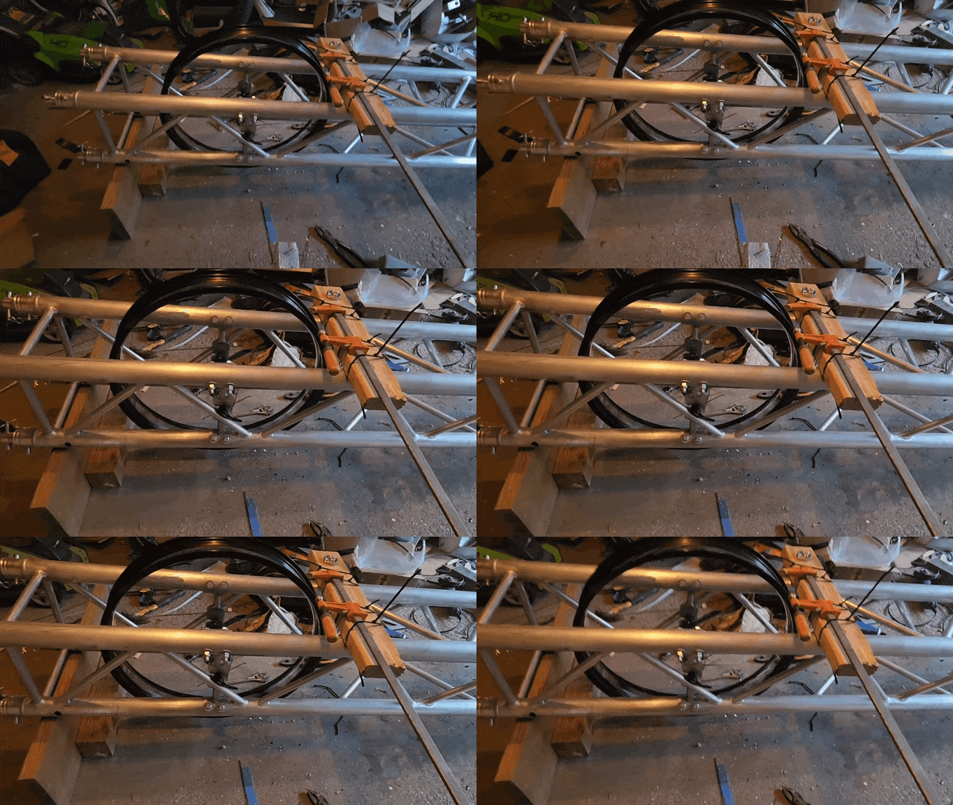
I jerry-rigged an adjustable indicator by zip-tying a clamp to the truss frame.
This gave me adjustability without having to reposition the entire rig every time. It was much easier to find the misalignments and correct them.
It still took 3 hours to get everything lined up. But now
🎵"This wheel is TRUE!"🎵
After getting the rim aligned, I put the tire back on the rim, attached the brake disc and drive sprocket, and mounted the rear wheel! The sculpture has been up on blocks for a long time. Finally, one of the wheels is on the bus!
The Front End
I re-mounted the differential using the new bushing plate/nose cone.
I noticed that the new plate still flexes a little when mounting. I'll wait until road testing, but we may have to make a thicker plate.
I modified the right side knuckle to reduce binding while turning and finished mounting both knuckles, including the Haim joints.
I also fabricated the steering plate and the pieces for the steering support. After our machine shop captain welded the support pieces together, I mounted the steering plate to the truss frame.
I made connectors for the tie rods that link the Haim joints on the knuckles with the steering plate. The connectors are joined using threaded rods.
The Front Wheels
I have been avoiding dealing with the front wheels. A solution for mounting the wheels on the CV axles had not revealed itself yet and there were many other "solvable" problems to address. But no longer.
The front wheel hubs came with 0.5" holes for standard bicycle axle bolts, but the CV joints that the wheels must attach to are 0.75" in diameter.
First I tried to drill the holes wider, but I barely made a dent. I started getting worried as this was my big idea to make the wheels work. I consulted with our machine shop captain and he discovered that the ends of the front wheel hubs were not solid but cups that could be removed. Huzzah!
Using a hammer and screwdriver we popped out the cups and now there's a 1.16" hole. And no drilling required (this time).
This helped us to finally work out how the CV axles will interface with the hubs. We designed sleeves to fit over the CV axle ends. The inside bore of the sleeves is significantly smaller than the CV diameter.
To mount them, we will heat the sleeves up until the inside holes expand wide enough to slip over the CV axle. They will snug up into a very tight press-fit as they cool.
We also designed a custom shoulder bolt that screws onto the end of the CV axle, securing the bicycle hub to the axle.
The hubs will slide over the sleeves and the bolts lock everything down. The bicycle hubs have a brake disc bolt pattern on their flanges. The brake disc attaches to these bolts, and a custom spacer helps align the disc.
CAM files were created for everything but the bolt and parts were made out of aluminum on the Tormach CNC mill.
I originally expected to keep the hubs on the wheels to save a lot of time, but the rims are in the way of some drilling that is needed to finish the work.
I took the hubs off of the front wheels to work without obstructions. But now that they are off, I decided to get new hubs.
The original hubs are front/rear, so they're two different sizes. They would require different parts in order to mount them.
I ordered two identical front hubs instead, in the spirit of standardization. I'll check the fit of the inside diameters when they arrive.
Hopefully, I can use the sleeves I already made. I won't need the brake disc spacer, since the new hubs already come with a flange for mounting brakes. I haven't made the CV bolts yet as I'm waiting to see if I have to make any adjustments.
The Hyperdrive
Meanwhile, I started assembling the Hyperdrive.
The axles are too short for some reason (It's me, hi. I'm the problem. It's me), so I ordered new ones. The short belts are a little too long, but I have enough adjustment in the hyperdrive to pick up that slack. Though, I may have to make a longer tensioner block to be able to use four screws. We'll see if that's actually a problem.
The long belt is also a little too long (but the next size down is way too short). I found a spot along the path of the long belt where I can add another idler pulley.
That should take up the extra length. I have to wait a week to get that part, so I'm putting a pin in that.
I won't idle while I'm waiting. Time to tackle the seats and pedals!
We are marching ever forward, though sometimes I feel like we're standing still. I've made a little bit of progress on a lot of things. First, the front and rear wheel supports have finally been mounted to the frame!
Now we just need mountable wheels! 🤔 The front wheels are still a bit of a question mark, so I worked on the rear wheel. I tried rebuilding the 26" rear wheel to use a rear hub (the tire originally had a front hub). It wasn't too bad for my first time. I watched a video on building bicycle wheels a few times and referred to it while working.
Then an issue revealed itself. The video I watched was for a regular wheel, but we're using fat wheels on the Falcon. The spoke pattern is slightly different than a regular wheel. Suddenly, I was lost and the wheel was in pieces.
Luckily, I had two of these tires. The second wheel was a great guide for placing the spokes correctly into the rim. And I was able to finish installing the spokes. However, the original spokes turned out to be about 10mm too long for the new hub.
I had measured and compared the original and new hubs and thought it would work, but I thought wrong. And so it goes with kinetic sculptures: expect modifications to the modifications. New, shorter spokes were ordered. And I rebuilt the wheel with the correctly sized spokes.
Now I have to true it. There is a truing stand in Lowell Makes' Bike Shop and videos on how to use it on YouTube. Once it is balanced, I will finally be ready to mount the rear wheel!! Yay!
Stiff Knuckles
I also addressed the problem of the stiff knuckles on the front, left side. The knuckles allow the wheels to change direction while allowing the wheel to spin. This is key to the front-wheel steering. I discovered during the first dry-fit that the front suspension had warped a bit during welding and the space where the knuckle sits shrank by .150".
The knuckle brackets have ledges where the bearing plate attaches. At first, I thought I could mill those ledges down, but I realized that wouldn't work. Doing that would also require modifying the bearing plate. Too much work.
Instead, I lowered the counterbores on top of the brackets. I hesitated doing it this way initially, because I thought it would be harder. But it only took 5 minutes to make the change to the 3D model and another 5 minutes to run the update on the Tormach. Easy Pease.
The knuckle moves so well now that I'm going to do the same thing to the knuckle brackets on the right side.
Hyperdrive Assembly
We made some strides on the Hyperdrive, the heart of the Falcon's drive train.
All the bearing cups were pressed into the frame and tensioner blocks. Our machine shop captain then welded the cups to the frames.
After welding, I pressed the bearings into the tensioner blocks to confirm that the axles actually fit through the blocks. So far, so good.
I also drilled 1/2" holes into all the pulleys, so they can be mounted on the bearings.
However, I realized while I was doing this that the pulleys do NOT have set screws. This means they cannot currently be locked to the axle. smh. I've been staring at these things for months--MONTHS--and still I missed it. Sigh. It's not world-ending. I just had to drill and tap holes in the pulleys for set screws. But it's another step that takes time.
I almost finished putting set screws into all the pulleys, but then I managed to break two taps in two minutes. And it broke low in the holes I was tapping, so they are sticking slightly into the axle hole. Now I have to drill out those holes to remove the offending tap material. Yet another step.
Differential Alignment
Also during the first dry-fit, I mounted the bushing plates I designed for the modified lawnmower differential. I eventually got it to spin freely, but I had to tune its alignment like a drum--turning nuts a bit at a time while checking the spin. The alignment was so sensitive that I know road conditions would definitely knock the differential out of tune.
I realized that all the bushings had to sit on a common surface. They would then stay aligned to each other without needing fine adjustment. This is actually how the original differential case works, so that should have been a clue.
I then designed a single plate that attaches to the existing brackets and has mounting holes for all the bushing blocks. But it couldn't just be a plate with holes in it, right? It had to feel a little more Falcon than that.
Once I was happy with the new design, I used the Tormach to make it.
Because the shafts are longer than the mounting area, I had to first place the bushings on the shafts and then bolt the bushings to the plate. It works pretty well now. There's still a slight stiffness, but I think lubrication will correct that.
After this test fit, I had to take the differential off one more time, all because of Marisa Tomei.
My Cousin Vinny was on the other day. Marisa Tomei is giving her testimony that saves Vinny's cousin and it ended up saving me, too.
LOL, she's right. The Falcon has a regular differential. So, the Falcon's front tires will do the same thing as a '64 Buick Skylark. One wheel will spin while the other one does nothing. Well, we can't do a limited-slip differential, but we can do a locking differential.
To make it spin like one solid axle (locking), I modified the design of the sprocket adapter plate (the plate bolted on the left side of the sprocket in the image above). I added another hub on that side then drilled and tapped holes for a set screw.
Now when I want to turn the Falcon into a mud crawler, I just need to screw down the set screw and Viola! And it's all thanks to Marisa Tomei! 😁



.png)


.png)
.png)
.png)
.jpg)



